The Risk Based Inspection module of our NO-LEAK solution is able to perform the Semi-Quantitative Risk Assessment on piping and pressure vessels carrying water, oil, and gas fluids. It is anticipated that failure of any of these critical equipment could have dire consequences on the Asset’s HSE goals. Thus, in line with API 581 (amongst other international standards), this module ensures that the ‘Probability of Failure’ and ‘Consequence of Failure’ is accurately calculated whilst ensuring the correct Inspection frequency is specified.
The Fitness for Service Assessment module encompasses the assessments for the following equipment in line with various applicable codes and standards –
This module was specifically designed to manage Cathodic Protection designs and remote monitoring of Cathodic Protection systems by both impressed and sacrificial systems.
Existing remote Cathodic Protection monitoring units can be connected to this module.
This module of the NO-LEAK solution was specifically designed for the management of Internal Corrosion.
We designed it because we noticed that in most Assets, Operators were not connecting the increased internal degradation rate to the increased inspection frequency – We thus hope that module helps operators quickly detect when their site activities are resulting in increased degradation rate beyond the prediction of the Risk Based Inspection module.
This module is aimed at planning and keeping track of all well integrity activities alongside using the Swiss Cheese assessment technique to note failure points requiring immediate actions.
It is quite necessary to ensure the optimal operation of the wells as they are one of the most critical component of an Oil and Gas Asset.
It thus helps detail the current status of the Wells within an Asset.
This module is generally a reporting tool aimed at assisting Operators which do not have and Plant Maintenance CMMS solution aimed at recording or raising anomalies requiring actions or temporary deviations implemented on site.
It is divided into 2 namely:
Defect Management It is aimed at managing Integrity and Non-Integrity related defect anomalies. Within this section, Operators will be able to keep track of all defects on all Equipment. For Operators having a Cloud-based CMMS system, we are also able to remotely connect to it in order to either obtain or send data to the CMMS system.
Deviation Management It is aimed at managing all temporary actions implemented by the production teams on site, due to operational issues. With this section, Operator’s Asset Integrity personnel are able to keep track of issues within their Assets.
ANOMALY MANAGEMENT
This section is divided into 2 namely:
Defect Management It is aimed at managing Integrity and Non-Integrity related defect anomalies. Within this section, operators will be able to keep track of all defects in the pressurized equipment and ensure that all equipment operates within their respective integrity operating windows.
Deviation Management It is aimed at managing all anomalies due to operational issues. With this section, operators can keep track of issues which should be rectified at a future date.
FMECA ASSESSMENT MODULE
This module is aimed at ensuring all non-pressurized equipment are effectively assessed for its attendant criticality to the entire system. At the end of the assessment, Operators will be able to identify all non-pressurized Equipment which are important for the Asset to be functional enough to achieve the planned operational design.
SAFETY DEVICES MODULE
This module is aimed at ensuring Operators are able to manage the movement and Integrity of all Safety Devices.
It thus tracks and reports on all Safety devices thus ensuring all Safety devices (PSVs, TSVs, PVSVs, Bursting Disks, etc.)’s replacement, testing, and repairs are managed optimally in line with the required regulatory requirements.
PRESSURE AND TEMPERATURE SAFETY DEVICE MANAGEMENT
This section is aimed at ensuring all PSVs, TSVs, PVSVs, etc. replacement, testing, and repairs are managed optimally in line with the required regulatory requirements.
IOW MODULE
This module manages all pressurized equipment in a system manner and eases the management of these systems.
It helps instill the system-based review of equipment condition within a system volume.
With this section, a system status managed as each Equipment within a System contributes to the functionality of the system.
In the same manner, an Equipment’s failure within the group, affects the functionality of the System.
SECE MODULE
This module helps Senior Management keep track of the condition of high-risk equipment which could damage the organization’s production, and reputation if it fails during operation.
For an equipment to enter into this categorization, its loss of containment must have a high consequence on the Asset’s production or the Operator’s reputation.
From experience, about 8-15% of all Equipment in an Asset, are typically categorized as SECE.
SAFETY, ENVIRONMENT, CRITICAL ELEMENT MANAGEMENT
This section ensures Senior Management constantly has an overview of the condition of high-risk equipment which could damage the organization’s reputation if it fails on site.
PRESCRIPTIVE INSPECTION MODULE
This module was strategically created for Operators with no CMMS.
It is aimed at planning all Inspection and Maintenance activities to be carried out on any Equipment in an Asset, in line with prescriptive requirements.
Feedback
John Heitz
Thank you very much for the great service! I feel your company provides a good user interface. The process was simple and easy to use! –
Amar Kahul
The calculators in the website have really helped me and our business. Man, this thing is getting better and better as I learn more about it. –
Bob Jones
GeekyExperts are the best! The calculators are free to use and really simple, also you can get a lot of books in their shop! –
This application shall be able to perform the Risk Assessment of piping and pressure vessels carrying water, oil, and gas fluids. It is anticipated that failure of these equipment could have dire consequences on both living and non-living things alike hence, in line with international standards, the Application ensures that the ‘Probability of Failure’ and ‘Consequence of Failure’ is accurately predicted whilst performing the Risk Assessment for each equipment.
The modelled ‘Corrosion Mechanisms’ are as listed below:
Default Internal Corrosion
Microbiologically Induced Corrosion
Sweet Corrosion
Cooling Water Corrosion
Acid Sour Water Corrosion
Amine Stress Corrosion Cracking
Hydrofluoric Acid Corrosion
Sulfuric Acid Corrosion
High Temperature (H2/H2S) Corrosion
Hydrochloric Acid Corrosion
External Corrosion
External – Corrosion Under Insulation
The modelled Probability of Failure considers the following:
Site Management procedures and operational documentation implementation including its HSE practices.
Damage Families
Historically documented failure frequencies
The modelled Consequence of Failure considers the following:
Equipment Repair Costs include an extra factor for importation.
Environmental including potential leak cleanup Consequences.
Business Impact Consequences
Personnel Impact Consequences
Flammable and Explosive Consequences, etc.
The modelled Risk Assessment is a 5 X 5 risk assessment with description as follows –
Probability of Failure (1 – 5) o 1 – Least Probability of Failure o 5 – Highest Probability of Failure
Consequences of Failure (A – E) o A – Least Consequence of Failure o E – Highest Consequences of Failure
The modelled Inspection Planning typically considers the following in predicting the inspection plan:
Probability of Failure
Consequence of Failure
Risk Assessment
Fitness for Service Assessment of current defects noticed after inspection.
In determining – ➢ Major Inspection o Intrusive – Pressure Vessel o Non-Intrusive – Piping and Pressure Vessel ➢ Intermediate Inspection o Non-Intrusive – Piping and Pressure Vessel
The reference standards implemented for the various sub-sections of the Risk Based Inspection section are as itemized below:
Required Input Parameters – As specified by API 581, 3 rd Edition, April 2019, and ASME PCC-3 (2017)
Corrosion Mechanism Assessments – As specified by API 571, 3rd Edition, March 2019, and ASME PCC-3 (2017)
Damage Families, Probability of Failure, Consequence of Failure, Risk Assessments – As specified by API 581, 3rd Edition, April 2019, and ASME PCC-3 (2017)
Inspection Planning – As specified by API 581 (3rd Edition, April 2019), DNV RP G101 (2010), Mineral Oil Safety Regulation (2004) and ASME PCC-3 (2017)
FITNESS FOR SERVICE ASSESSMENTS
The Fitness for Service Assessment section encompasses the assessments for the following equipment –
Piping
Pressure Vessel
Pipelines
The Pipelines are assessed in line with 2 methods – ASME B31G, Modified and RSTRENG methodology.
SME B31G Modified Methodology: With this, we are able confirm the maximum pressure a pipeline can hold with respect to the damage noted after inspection. With this methodology, a pipeline can be assessed to confirm how critical its in-service damage is. This methodology has 2 levels in the application generally referred to as Level I and Level II.
RSTRENG Methodology: With this, we can perform the same assessment detailed above in ASME B31G methodology. However, there is only one level.
The Piping and Pressure Vessel section is in line with the API 579 Assessment Methodology. With its assessment, oil and gas operators can determine the maximum pressure a piping or a pressure vessel should be operated after a corrosion related damage has been assessed. The reference standards implemented for the Fitness for Service section are as itemized below:
Piping and Pressure Vessel – As specified in API 579-2/ASME FFS-2, August 2009
Pipeline – As specified in ASME B31G (Modified)-2023, RSTRENG and NACE SP 0192 (2012)
CATHODIC PROTECTION DESIGN
This section is specifically created to cater for the Cathodic Protection design by both impressed and sacrificial systems, but the impressed current system has not been implemented. We are thus providing cathodic protection designs for only the sacrificial systems. The sacrificial system is designed to cater for the following:
Internals of Equipment – Pressure Vessels, Tanks and Hulls either with or without Bacteria
External of Equipment – Buried in Soil or submerged in water.
With this, Clients can determine:
The number of Anodes required to protect the equipment
The minimum weight of the Anodes required to protect an equipment for the design life
In line with best practice, 4 sacrificial anode installation methods were designed
Long Slender Stand-Off Anodes (Length >/= 4 times the radius)
Short Slender Stand-Off Anodes (Length < 4 times the radius)
Long flush mouthed Anodes (Length >/= 4 times width or Length > 4 times the thickness)
Short Flush Mouthed Anodes or Bracelet Anodes or other types of Anodes
The reference standards implemented in this section are as detailed below:
DNV RP B401, October (2010) – For Sea Water and Fresh Water Systems (Internal and External)
NACE SP 0169 (2013) – For Onshore and Offshore Systems with reference to bacteria environments.
NACE RP 0285 (2011) – Inputs for Onshore buried Equipment cathodic Protection Design
NACE RP 0186 (2007) – Some inputs were gotten from this document for the External Cathodic Protection design.
NACE TM0497 (2018) – Some details were gotten from this document for the document in relation to protection criteria
INTERNAL CORROSION MANAGEMENT
This section of the Application is specifically directed at internal corrosion management. It is further divided into 2 sections:
The internal Corrosion Monitoring Equipment Assessment sub-section is aimed at confirming the corrosivity of the fluid on the corrosion loop that the monitoring equipmentis installed. Its assessment calculates the General corrosion rate based on the weight loss and the pitting rate in line with the NACE International standard after which the values are graded in severity.
The Chemical Treatment Assessment sub-section is aimed at confirming how efficient the Asset’s chemical treatments is performing. The following are typically a minimum of what this section shall be able to assess:
Efficiency of Biocide Injections (All Systems) – Bacteria Count Assessments
Efficiency of Corrosion Inhibitor Injections (All Systems) – Iron Counts Assessments
Gas Systems – pH Stabilization Assessments
Cold / Hot Water Systems – Residual Corrosion Parameters Assessments
Water Injection Systems – Residual Corrosion Parameters Assessments
The above 2 sub-assessments were based on the following standards:
Internal Corrosion Monitoring Equipment – NACE RP 0775 (2023)
Chemical Treatment Assessments – Based on NACE SP0192 (2012), NACE International’s
Professionals, NACE Certified Treatment Specialists, etc.
WELL INTEGRITY MANAGEMENT
This section of the Application is aimed at planning all well integrity activities necessary to ensure the optimal operation of the wells. It also details the status (Integrity, Operational or otherwise), of the Well.
Integrity related tasks under the well integrity management section are as follows:
Annulus Pressure Monitoring o Annulus Pressure(s) o Bleed-Off Details
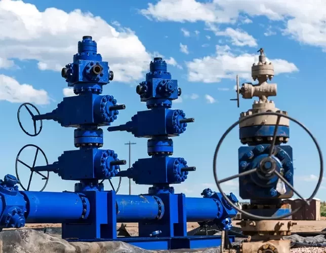
Choke and Manifold Valves o Choke Valve o Riser Valve o Production Manifold Valve o Test Manifold Valve
Downhole and Surface Valve Testing o Surface Control Subsurface Safety Valve o Lower Manifold Valve o Surface Safety Valve o Lower Wing Valve o Surface Valve
X-Mas Tree and Wellhead Greasing Inspection o Greasing Date and Frequency